
Sometimes in your projects you simply do not have enough I/O lines available, take for example a lot of the multiple LED examples, these use 8 outputs to control 8 LEDs via your Wemos Mini, that can restrict the amount of outputs you would have available to drive other devices. Instead of this we can use a shift register, in this case a 74HC595 and using 3 I/O pins we can control 8 LED’s, that’s a saving of 5 I/O pins for other uses.
You can use it to control 8 outputs at a time while only taking up a few pins on your microcontroller. You can link multiple registers together to extend your output even more. The 74HC595 has an 8 bit storage register and an 8 bit shift register. Data is written to the shift register serially, then latched onto the storage register. The storage register then controls 8 output lines
Lets look at the 74HC595
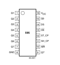
| PINS 1-7, 15 | Q0 to Q7 | Output Pins |
| PIN 8 | GND | Ground, Vss |
| PIN 9 | Q7″ | Serial Out |
| PIN 10 | MR | Master Reclear, active low |
| PIN 11 | SH_CP | Shift register clock pin |
| PIN 12 | ST_CP | Storage register clock pin (latch pin) |
| PIN 13 | OE | Output enable, active low |
| PIN 14 | DS | Serial data input |
| PIN 16 | Vcc | Positive supply voltage 3.3v |
Parts List
Here are the parts I used
| Name | Links | |
| Wemos Mini | ||
| 74HC595 | ||
| Connecting cables |
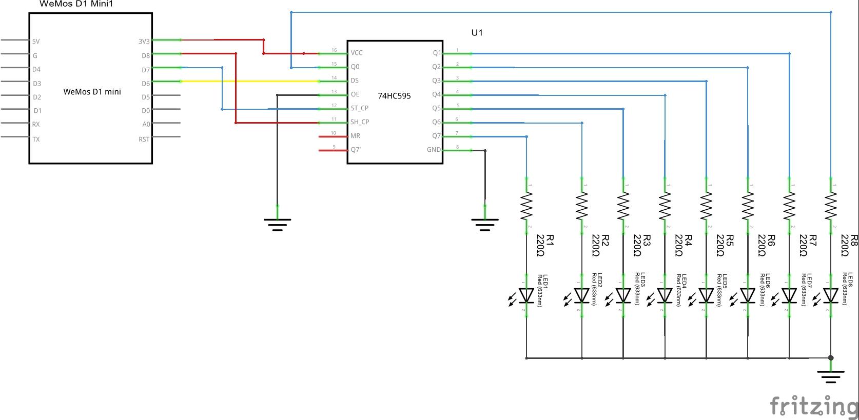
Schematic
This is the schematic on how to control the 74HC595 from your Wemos Mini and how to wire up 8 sets of LEDs to the 74HC595.
I’ve connected the Vcc of the 74HC595 to the 3v3 output of the Wemos mini just to illustrate that we are using 3.3v for the 74HC595
Code
In this example we will simply display a random value on the LEDs, this will also show how to generate a random number.
int latchPin = D8;
int clockPin = D7;
int dataPin = D6;
long randNumber;

void setup()
{
//set pins to output so you can control the shift register
pinMode(latchPin, OUTPUT);
pinMode(clockPin, OUTPUT);
pinMode(dataPin, OUTPUT);
randomSeed(analogRead(A0));
}

void loop()
{
randNumber = random(1, 255);
// take the latchPin low so
// the LEDs don't change while you're sending in bits:
digitalWrite(latchPin, LOW);
// shift out the bits:
shiftOut(dataPin, clockPin, MSBFIRST, randNumber);
//take the latch pin high so the LEDs will light up:
digitalWrite(latchPin, HIGH);
// pause before next value:
delay(500);
}

Hey there, thanks for your great example.
You switched D8 and D7:
Latch Pin in Code is D8
Clock Pin in Code is D7
In your shematic the
ST_CP Storage Clock Pin (Latch) is D7
SH_CP Shift Register Clock is D8