
In this article we look at a LTR390 UV Light Sensor and we will connect it to a Wemos Mini
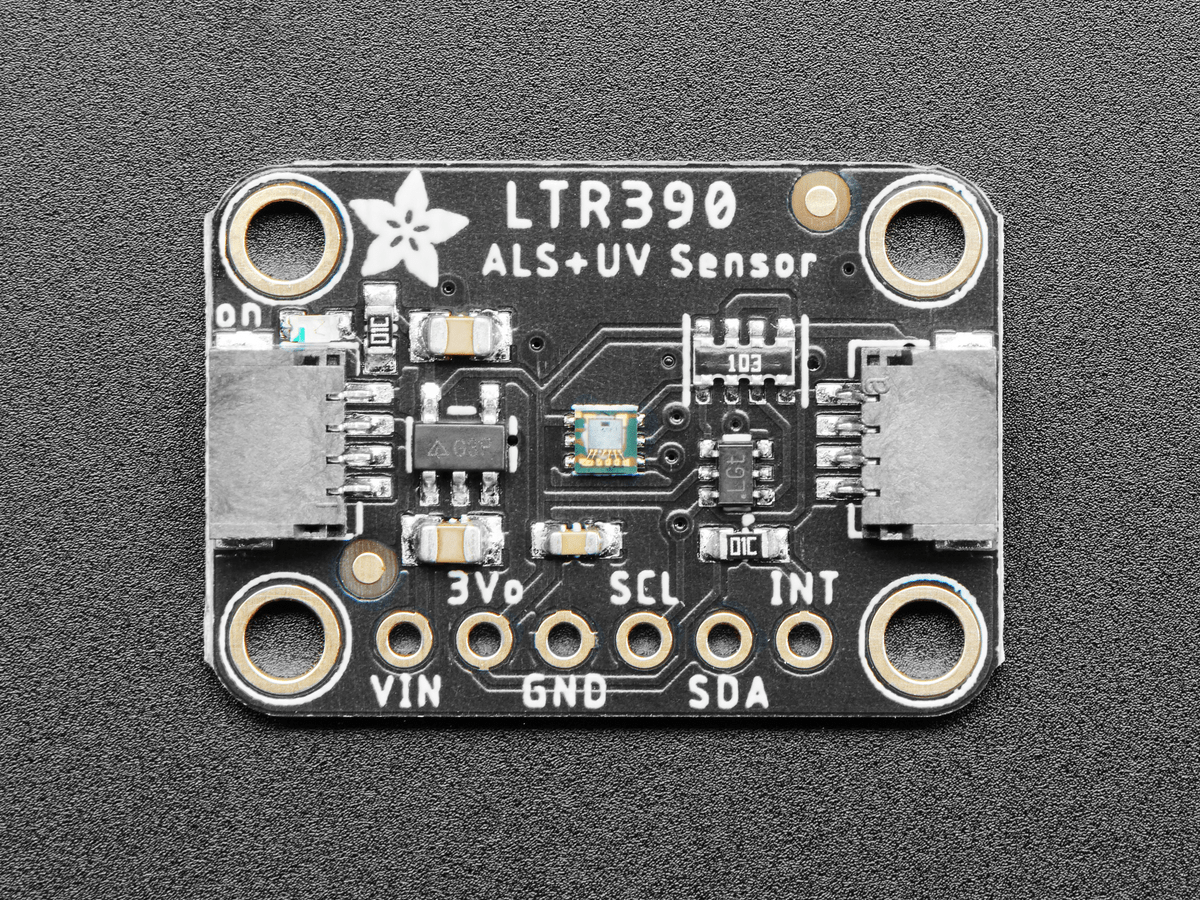
First lets look at the sensor
This sensor converts light intensity to a digital output signal capable of direct I2C interface.
It provides a linear ALS response over a wide dynamic range, and is well suited to applications under high ambient brightness.
The sensor has a programmable interrupt with hysteresis to response to events and that removes the need to poll the sensor for a reading which improves system efficiency.
This CMOS design and factory-set one time trimming capability ensure minimal sensor-to-sensor variations for ease of manufacturability to the end customers.
Features
I2C interface capable of Standard mode @100kHz or Fast mode @400kHz communication; 1.8V logic compatible
Ambient Light / Ultraviolet light(UVS)Technology in one ultra-small 2x2mm ChipLED package
Very low power consumption with sleep mode capability
Operating voltage ranges: 1.7V to 3.6V
Operating temperature ranges: -40 to +85 ºC
Built-in temperature compensation circuit
Programmable interrupt function for ALS , UVS with upper and lower thresholds
UVS/ALS Features
- 13 to 20 bits effective resolution
- Wide dynamic range of 1:18,000,000 with linear response
- Close to human eye spectral response
- Automatic rejection for 50Hz/60Hz lighting flicker
This is the sensor that I bought
Parts List
Here are the parts I used
| Name | Links | |
| Wemos Mini | ||
| LTR390 | ||
| Connecting cables |
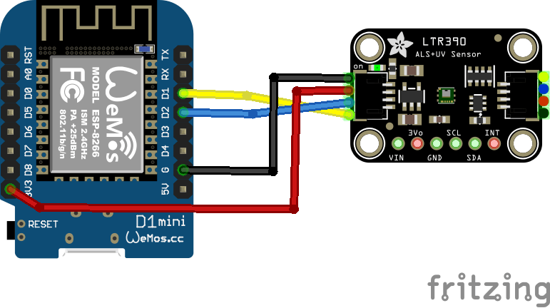
Schematic/Connection
I used the Adafruit LTR390 sensor and in this case used the Stemma connection on the sensor
For the STEMMA QT cables, it uses the Qwiic convention:
Black for GND
Red for V+
Blue for SDA
Yellow for SCL
So color coded for ease of use, this layout shows a connection to the module
Code Example
This uses the library from Adafruit LTR390 library and you will also need the Adafruit BusIO library installed using the Library Manager in the Arduino IDE.
This is the default example
#include "Adafruit_LTR390.h"

Adafruit_LTR390 ltr = Adafruit_LTR390();

void setup() {
  Serial.begin(115200);
  Serial.println("Adafruit LTR-390 test");

  if ( ! ltr.begin() ) {
    Serial.println("Couldn't find LTR sensor!");
    while (1) delay(10);
  }
  Serial.println("Found LTR sensor!");

  ltr.setMode(LTR390_MODE_UVS);
  if (ltr.getMode() == LTR390_MODE_ALS) {
    Serial.println("In ALS mode");
  } else {
    Serial.println("In UVS mode");
  }

  ltr.setGain(LTR390_GAIN_3);
  Serial.print("Gain : ");
  switch (ltr.getGain()) {
    case LTR390_GAIN_1: Serial.println(1); break;
    case LTR390_GAIN_3: Serial.println(3); break;
    case LTR390_GAIN_6: Serial.println(6); break;
    case LTR390_GAIN_9: Serial.println(9); break;
    case LTR390_GAIN_18: Serial.println(18); break;
  }

  ltr.setResolution(LTR390_RESOLUTION_16BIT);
  Serial.print("Resolution : ");
  switch (ltr.getResolution()) {
    case LTR390_RESOLUTION_13BIT: Serial.println(13); break;
    case LTR390_RESOLUTION_16BIT: Serial.println(16); break;
    case LTR390_RESOLUTION_17BIT: Serial.println(17); break;
    case LTR390_RESOLUTION_18BIT: Serial.println(18); break;
    case LTR390_RESOLUTION_19BIT: Serial.println(19); break;
    case LTR390_RESOLUTION_20BIT: Serial.println(20); break;
  }

  ltr.setThresholds(100, 1000);
  ltr.configInterrupt(true, LTR390_MODE_UVS);
}

void loop()
{
  if (ltr.newDataAvailable())
  {
      Serial.print("UV data: ");
      Serial.println(ltr.readUVS());
  }

  delay(100);
}
Output
Open the serial monitor and you should see something like this. I was indoors at the time
UV data: 0
UV data: 0
UV data: 0
UV data: 0
UV data: 0
UV data: 0
Links